Traditional Multiplexing
Display multiplexing is very different from multiplexing used in data transmission, although it has the same basic principles. In display multiplexing, the data lines of the displays are connected together in parallel to a common bus on the microconroller. Then, the displays are turned on individually and addresses when they turn on. This allows one to use fewer I/O pins than it would normally take to drive the same amount of displays directly.
When using Charlieplexing, n drive pins can drive n digits with n-1 segments. When simplified, it equates to n pins being able to drive n2-n segments or LED’s. Traditional multiplexing takes many more pins to drive the same amount of LED’s; 2n pins must be used to drive n2 LED’s.
Charlieplexing
Complementary Drive
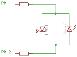
Charlieplexing, in its simplest forum, works using a matrix of complementary pairs of LED’s. The simplest possible Charlieplexed matrix would look like this:
Expanding: Tri-state Logic
If we were to expand this circuit to accommodate 3 pins and 6 LED’s, it would look like this:
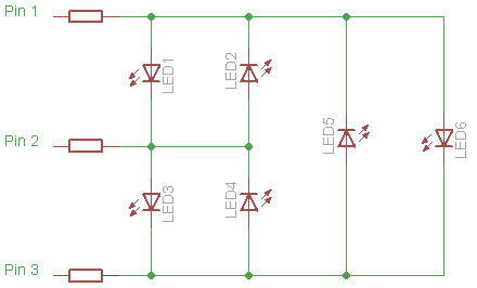
By using tri-state logic, the matrix can theoretically be expanded to any size, as long as pins are available. Any LED can be lit by applying 5V and 0V to its corresponding pins and setting all of the other pins connected to the matrix to input mode.
Problems with Charlieplexing
-
Duty cycle
Because only one LED is let at any given time, Charlieplexing requires much faster display refreshing than a traditionally multiplexed display. In order for a display to not have any noticeable flicker, the duty cycle for each LED must be greater than 50Hz. With traditional multiplexing this usually isn’t a problem because each digit or set of LED’s is turned on individually. Thus, the minimum duty cycle of a display is the number of digits times 50Hz. For a 20 LED display arranged in a traditional 4×5 matrix, the duty cycle is only 200Hz. With a charlieplexed display, each LED is lit individually, thus the duty cycle must me at minimum the number of LED’s times 50Hz. For the same 20 LED display from above, arranged in a charlieplex matrix, the overall duty cycle is 1000Hz.
-
Peak Current
Due to the increased duty cycle, the current requirement of a display increases much faster than it would with a traditionally multiplexed display. As the display gets larger, the average current flowing through the LED must be constant in order for it to maintain constant brightness, thus requiring the peak current to increase proportionally. This puts a limit to the size of the display, as when the peak current flowing through the LED’s when they’re turned on exceeds the LED’s ratings, Charlieplexing is not a possibility.
-
Complexity
Charlieplex matrices are much more complicated to lay out than are traditional multiplex matricies. This increases both cost of production and design time.
-
Forward Voltage
When using LED’s with different forward voltages, like when using different color LED’s, problems can exist where other LED’s will light when not wanted to.If we look at the diagram above we notice that if LED 6 has a four volt forward voltage, and LED’s 1 and 3 have forward voltages of two volts or less, they will light when LED 6 is intended to, as their current path is shorter. This issue can easily be avoided by checking the forward voltages of the LED’s used in the matrix and checking for compatibility issues. Or, more simply, using LED’s that have the same forward voltage.

Recent Comments